SPC Series
EMI / RFI Filters
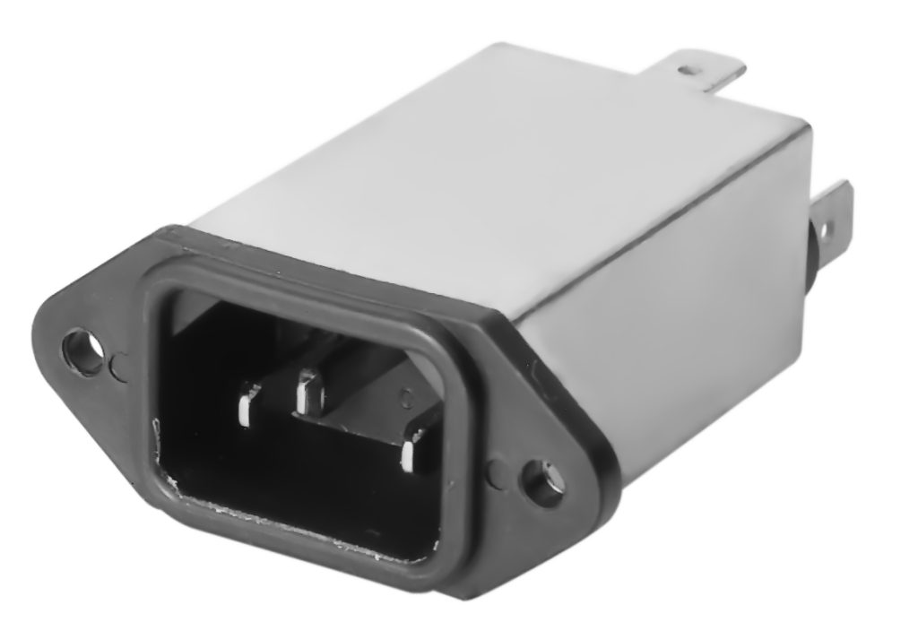
IEC-320 C14 Inlet Super Performance Line Filters
1-6 Amp Panel Mount Package
Specifications
| Voltage rating: | 115/250 VAC |
|---|---|
| Line frequency: | 50/60 Hz |
| Leakage current (line to ground): | 0.25 mA maximum at 115 V, 60 Hz 0.50 mA maximum at 250 V, 50 Hz |
| Test Voltage: | Line to ground, 2250 VDC Line to line, 1450 VDC |
| OverCurrent Test: | 6X rated for 8 sec. |
| Insulation: | 6000megohms/100VDC Resisance |
Applications
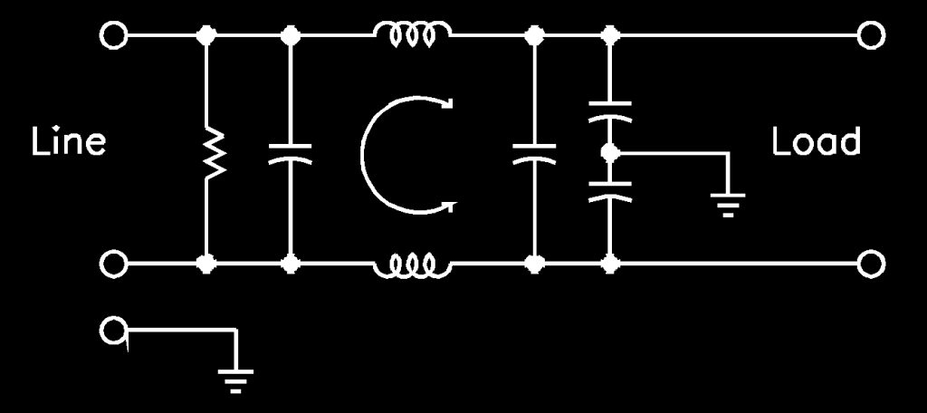
The SPC series super-performance power line filters give extremely high attenuation of both common and differential mode signals. These filters are an extension of the HPC series high-performance connector filters, having the same circuit with line-to-line capacitors on both line and load side. This enhances the differential mode, while the common mode remains essentially the same. The increased performance is useful in both susceptibility and emission control applications, in which maximum performance is desired.
The series is offered at 1, 3 or 6 amps. The SPC series is suitable for all types of electronic equipment. The EMI filter at the power source maximizes electromagnetic interference suppression and eliminates the need for wiring a separate filter to a power receptacle, thereby lowering the cost and improving the installation performance due to a reduction in stray wiring radiated susceptibility.
Certifications
UL File No. E62459, CSA File No. LR56661.
Electrical Schematic
How To Define A Part Number
| Series | Case Style | - | Current Rating |
|---|---|---|---|
| SPC | A | - | 1 |
Performance
| Current Rating | Frequency (MHz) | |||||||||
|---|---|---|---|---|---|---|---|---|---|---|
| Common Mode | 0.01 | 0.02 | 0.05 | 0.15 | 0.5 | 1 | 5 | 10 | 20 | 30 |
| 1A | 20 | 24 | 30 | 40 | 50 | 60 | 60 | 60 | 50 | 50 (db) |
| 3A | 5 | 10 | 20 | 30 | 35 | 45 | 55 | 60 | 50 | 50 (db) |
| 6A | 3 | 6 | 10 | 18 | 25 | 35 | 45 | 50 | 50 | 50 (db) |
| Differential Mode | ||||||||||
| 1A | 0 | 0 | 2 | 10 | 34 | 55 | 60 | 60 | 45 | 45 (db) |
| 3A | 0 | 0 | 2 | 8 | 27 | 45 | 55 | 55 | 45 | 45 (db) |
| 6A | 0 | 0 | 2 | 9 | 15 | 40 | 55 | 55 | 45 | 45 (db) |
Minimum insertion loss in 50 ohm system per MIL-STD-220A.
Ordering Information
| Current Rating | Part Number | Dimensions (mm) | ||||
|---|---|---|---|---|---|---|
| A | B** | C | D | E | ||
| 1A | SPCA-1* | 50.80 | 29.72 | 20.57 | 39.88 | 50.04 |
| SPCB-1* | 50.80 | 29.72 | 20.57 | 39.88 | 50.04 | |
| 3A | SPCA-3* | 50.80 | 29.72 | 20.57 | 39.88 | 50.04 |
| SPCB-3* | 50.80 | 29.72 | 20.57 | 39.88 | 50.04 | |
| 6A | SPCA-6* | 50.80 | 29.72 | 20.57 | 39.88 | 50.04 |
| SPCB-6* | 50.80 | 29.72 | 20.57 | 39.88 | 50.04 | |
* For small solder lug termination, add the suffix “L”, e.g, SPCA-1L (1.43mm Length)
** B dimensions listed are maximums
For 4.25” wire leads replacing terminals add a W to the end of any part number. For other wire lengths, check with factory.
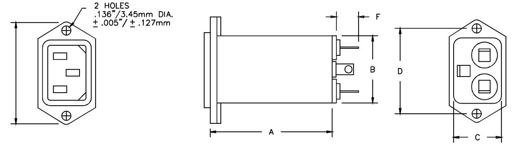
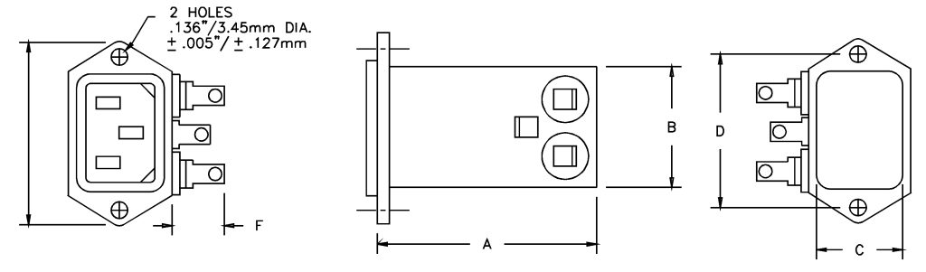
Case Styles
Style A
Style B
F Dimensions defined as 0.250 Tab Terminals (14.73mm Length, hole diameter 1.98mm)
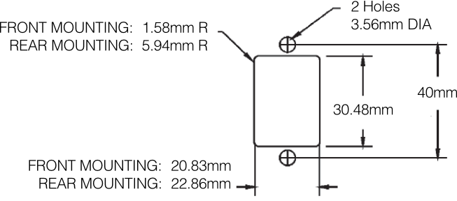
PANEL CUT-OUT
Specifications subject to change.